
What this guide is for
“CNC machining” is too broad to be a useful sourcing specification by itself. The buyer’s real problem may be machining a near-net investment casting, qualifying an alternate supplier for a forging, holding concentric bores on a rotating component, controlling sealing faces on a valve body, producing many low-volume part numbers, or adding local stocking to a repeat OEM program.
This guide organizes CNC machining around those decisions. It is written for procurement, design, manufacturing and quality teams that need repeatable finished parts, not merely machine time.
At China Precision Metal, our published machining scope includes 40+ CNC machines covering turning, milling, turn-mill, HMC, VMC and 3/4/5-axis work, with additional grinding, drilling/tapping, sinker EDM and wire EDM resources. Our core work includes machining castings and forgings, fully machined castings, industrial flow components, HMLV programs, second-source qualification and downstream inspection/functional verification.
CNC machining in one decision table
| Buyer question | Preferred approach |
|---|---|
| Is the geometry mostly rotational? | CNC turning or turn-mill may reduce setups |
| Are several prismatic faces/features required? | VMC/HMC or multi-axis milling depending access and lot size |
| Is the part complex but near-net castable? | Compare machined casting vs machining from billet |
| Is the blank forged? | Review forging stock, scale, distortion and datum condition before fixing the machining route |
| Are tolerances only critical in a few zones? | Keep general geometry economical and tighten only CTQ dimensions |
| Is the annual demand split into many small releases? | Quote annual volume + release pattern; consider HMLV fixtures/program control and stocking |
| Is it a second-source project? | Provide current starting form, drawing revision, inspection data and known process risks—not only target price |
1. Start with the starting form
A finished CNC part can begin as:
- bar or tube;
- plate or billet;
- investment casting;
- forging;
- sand/die casting or another near-net blank;
- customer-supplied semi-finished component.
Choosing the starting form is one of the highest-leverage cost decisions. Machining from solid avoids casting/forging tooling but may create heavy material waste and long cycle time. A near-net casting or forging adds upstream process controls but can dramatically reduce rough machining and integrate complex geometry.
The right answer depends on geometry, material, annual quantity, design maturity, structural requirements and the amount of material that would otherwise be removed.
2. Understand the major CNC routes
CNC turning
Turning is efficient for rotational diameters, shoulders, grooves, threads, bores and faces. Parts with a strong common axis often benefit from turning as an early datum-generating operation.
CNC milling
Milling creates prismatic faces, pockets, slots, bolt patterns, contoured surfaces and features located around multiple orientations.
Turn-mill
Turn-mill combines rotational and milled features in fewer handoffs. It can reduce reclamping error for parts that would otherwise move between lathe and mill.
VMC and HMC
Vertical and horizontal machining centers are selected according to geometry, fixture strategy, chip evacuation, pallet/production needs and access. HMCs can be particularly useful where multiple faces are machined around a fixture in repeat production.
4-axis and 5-axis machining
Additional axes improve access and can reduce the number of setups on complex parts. They are not automatically “better.” If a part can be produced reliably in simpler setups, added machine complexity may not add value.
EDM and grinding
Wire/sinker EDM and grinding serve specific geometries, hardened conditions or finish requirements that are inefficient with normal milling/turning. They are part of a process toolbox, not default operations.
3. Design the part around setups, not only features
Every time a part is reoriented, the process introduces another fixture condition and another opportunity for stack-up. A good DFM review asks:
- How many setups are actually required?
- Which datum can be established first?
- Can critical features be machined in the same clamping?
- Are there stable surfaces for workholding?
- Does the tool have physical access?
- Can the part be probed/inspected without losing datum logic?
- Is the part stiff enough under cutting and clamping loads?
Reducing setups can improve both cost and geometric consistency, but forcing everything into one complex setup can also be counterproductive. The process should be robust, not merely minimal.
4. Datum strategy is the backbone of repeatability
A tolerance only has meaning relative to a datum system. For machined castings and forgings, datum design is especially important because the blank has more geometric variation than precision-ground stock.
Useful principles include:
- establish stable primary/secondary/tertiary datums early;
- avoid locating a critical finished feature from an uncontrolled cosmetic casting surface;
- machine datum pads first where appropriate;
- keep critical coaxial or sealing relationships in as few datum transfers as practical;
- make inspection datums consistent with manufacturing datums where function allows.
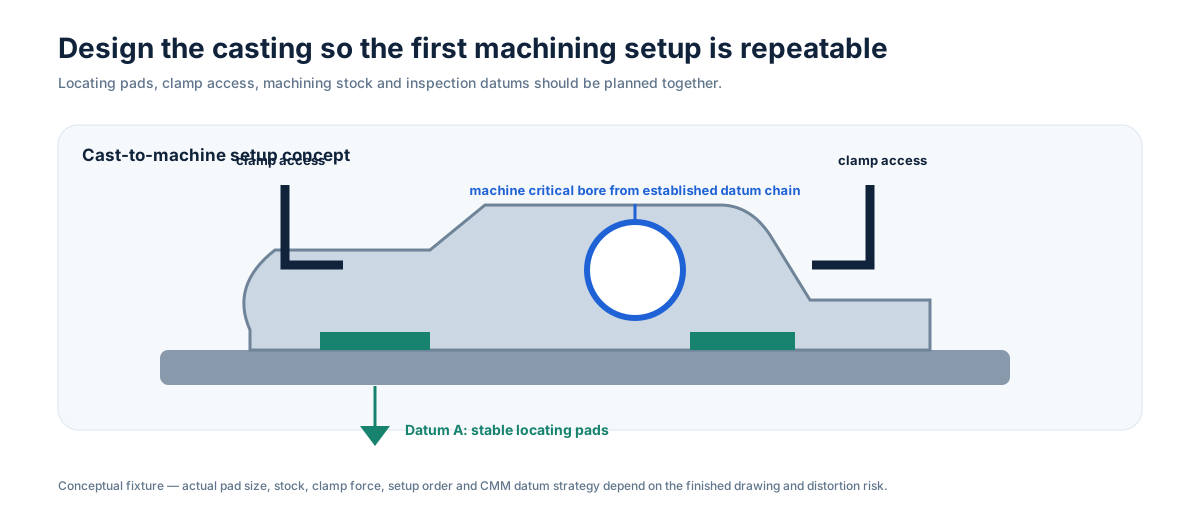
For castings, see Designing Castings for CNC Machining ↗.
5. Workholding and fixturing are part of the product design
The machine tool may be capable of micron-level motion, but the part still has to be held without shifting or distorting.
Fixture design must consider:
- available locating and clamping surfaces;
- component stiffness;
- thin-wall distortion;
- casting/forging variability;
- cutting-force direction;
- chip clearance;
- operator loading and poka-yoke;
- tool/probe access;
- repeat-lot fixture storage and identification.
For high-mix work, a fixture that is quick to identify, verify and re-use on the next release can be more valuable than a fixture optimized only for a single large batch.
6. Tolerances: tight only where function requires them
Unnecessarily tight tolerances increase cost because they can require:
- more stable material condition;
- additional semi-finish/finish operations;
- smaller cuts and more tool compensation;
- climate/temperature control;
- more capable fixturing;
- more inspection time;
- lower process yield.
Separate dimensions into:
- critical-to-function tolerances;
- fit/assembly tolerances;
- general manufacturing dimensions;
- reference/non-inspection dimensions.
If a tolerance controls sealing, bearing life, alignment or motion, keep it. If it exists only because CAD displayed many decimal places, review it.
7. GD&T can reduce ambiguity when the datum logic is good
Geometric controls are powerful when they express the real function. Position, flatness, perpendicularity, parallelism, runout, profile and concentric/coaxial relationships can be more useful than a chain of coordinate dimensions.
Poor GD&T can also make a part harder to quote than necessary. The drawing should establish:
- functional datums;
- the feature-control framework;
- which characteristics require reporting;
- whether bonus tolerance/material condition modifiers are intended;
- how the mating assembly actually uses the feature.
Supplier and customer should resolve ambiguous datum references before production, not during final inspection.
8. Holes, bores and threads need manufacturing context
Holes are not all equivalent. A through clearance hole, deep cross-hole, precision bearing bore and threaded pressure port have different tool-access and verification needs.
Clarify:
- through vs blind depth;
- bottom condition;
- thread standard/class and engagement length;
- counterbore/countersink geometry;
- bore cylindricity/roundness where functional;
- cross-hole breakout and burr control;
- whether a sealing thread or machined sealing face is involved;
- inspection gauge/report requirements.
Avoid modeling tiny decorative chamfers on every edge when a controlled deburr/break-edge note is sufficient for function.
9. Internal corners, pockets and tool reach
Rotating cutting tools naturally create internal radii. Deep narrow pockets require long tools, which are less stiff and more prone to vibration/deflection.
Design for:
- practical internal corner radii;
- tool diameter that can physically reach the feature;
- reasonable depth-to-width relationships;
- chip evacuation;
- inspection access;
- clearance for tool holders, not only the cutter tip.
A complex pocket that looks easy in CAD may require several tool lengths, special tooling or 5-axis access in production.
10. Thin walls and distortion
Thin walls can move under clamping, cutting force, residual stress and heat. This is especially important in stainless steel, large rings, thin flanges, castings after heat treatment and parts with large material removal.
Possible strategies include:
- leave temporary support stock;
- rough and semi-finish before final machining;
- balance material removal across the part;
- use softer/distributed clamping;
- allow stress stabilization between operations where needed;
- inspect after unclamping when the free-state dimension is what matters.
Do not specify a free-state flatness target without considering how the part is functionally mounted if the assembly intentionally constrains it.
11. Surface roughness must be tied to function
Not every machined surface needs the same Ra. Functional reasons may include:
- gasket or O-ring sealing;
- bearing/bushing fit;
- sliding wear;
- sanitary cleanability;
- fatigue-sensitive surface condition;
- cosmetic appearance.
Other faces only need normal as-machined quality and burr-free edges. Define roughness on the surfaces where it matters instead of applying one fine value to the whole part.
Machining marks and polishing are also different processes. A highly polished sanitary surface may require dedicated mechanical polishing and inspection after CNC machining.
12. Material machinability changes the route
A CNC quote should specify the exact material and condition because tool wear, heat generation, chip control and distortion can vary greatly.
Austenitic stainless steel
Common in pump, valve, sanitary and corrosion-service components. Work hardening, heat and burr behavior need appropriate tooling and cutting strategy.
Duplex / super duplex
Strength and corrosion-service requirements make heat treatment/material condition important. Machining strategy, ferrite/material verification and final corrosion-related requirements may need coordination.
17-4PH and precipitation-hardening stainless
The required heat-treatment condition affects hardness and machining sequence. Specify the final condition rather than only the alloy name.
Carbon and alloy steels
Machinability varies with grade, hardness and heat treatment. Forged or cast conditions can also introduce scale and stock variability that must be accounted for.
Nickel-based alloys
High tool loads and heat can make cycle time and tool consumption major cost drivers. Geometry should avoid unnecessary deep pockets or excess stock.
Aluminum, brass and other metals
These can be efficient to machine, but the exact alloy, temper and functional requirement still matter.
We also machine selected engineering plastics and hard rubber where appropriate, but their thermal and stiffness behavior requires different tolerance expectations from metals.
13. Machining investment castings: control the blank, then the feature
Machined castings combine two process capability systems. The casting must provide enough usable stock and stable datum geometry; the CNC route must convert that blank into the finished interfaces.
Review:
- casting dimensional variation;
- heat-treatment distortion;
- gate/grind locations;
- datum pads;
- local machining allowance;
- pressure-wall location;
- porosity exposure risk after machining;
- clamp access;
- finished-condition inspection.
A raw casting price comparison is incomplete if suppliers have different machining yield or stock strategy.
See Machined Castings ↗ and Machining Allowance ↗.
14. Machining forgings: understand stock and grain-driven design constraints
Forgings can provide strong mechanical properties, but machining still has to accommodate:
- flash/parting condition;
- stock variation;
- scale;
- distortion after heat treatment;
- draft/forged geometry;
- datum availability;
- the amount of material left on critical faces/bores.
For second-source work, provide the actual forging drawing/blank condition if it is controlled separately from the final machined drawing.
15. Machining from billet: simple commercially, not always cheapest physically
Billet machining can be ideal for prototypes, rapidly changing designs and simple parts. It avoids hard tooling and provides high freedom to modify geometry.
But for a complex steel or stainless part, the buyer should calculate:
- buy-to-fly/material-removal ratio;
- roughing time;
- tool wear;
- chip value vs raw material value;
- number of setups;
- whether a near-net casting/forging could eliminate most of the removed volume.
The cheapest process at 5 pieces may be different from the cheapest process at 500 recurring pieces.
16. Heat treatment and machining sequence
Heat treatment can change hardness and dimensions. The machining route may need to divide work into:
- rough machining before heat treatment;
- heat treatment;
- stabilization/straightening where permitted;
- finish machining of critical dimensions;
- final surface treatment/inspection.
The exact sequence depends on alloy, material standard and required properties. If hardness or corrosion performance is critical, the final condition should be explicit in the RFQ.
17. Deburring, marking, straightening and controlled repair
A finished CNC part often requires more than chip-making.
Possible downstream operations include:
- deburring and edge break;
- laser/mechanical part marking;
- cleaning;
- straightening/dimensional correction where technically appropriate;
- balancing for suitable rotating components;
- controlled laser-weld repair of permitted casting areas;
- blasting/polishing/passivation/electropolishing;
- assembly or sub-assembly where specified.
The drawing should identify prohibited repair zones, marking location/depth and cosmetic requirements when they matter.
18. Pressure-boundary machining needs finished-condition validation
Machining can open a subsurface casting discontinuity that was enclosed before stock removal. This is why pressure-boundary parts often need leak/pressure validation after the machining operations that establish the pressure wall or sealing interface.
The RFQ should define:
- service medium;
- test medium;
- test pressure/vacuum;
- hold time;
- allowable leak/loss or pass/fail rule;
- test stage;
- sampling frequency;
- documentation required.
See Pressure & Leak Testing ↗ and Leak-Tight Cast & Machined Components ↗.
19. Inspection strategy: do not inspect everything the same way
CNC quality plans should match feature risk.
Typical methods include:
- caliper/micrometer for accessible general dimensions;
- bore gauges and functional gauges;
- CMM for datum-related geometry and complex feature relationships;
- roughness measurement for controlled functional surfaces;
- hardness/material verification;
- balance verification for specified rotating parts;
- pressure/leak testing for fluid-boundary components;
- first-article or dimensional reports to the agreed characteristic list.
Our core dimensional resources include Hexagon and Mitutoyo CMMs. See Inspection Equipment ↗.
20. Measurement method must match the drawing intent
Disputes often occur because supplier and customer measure the same feature differently. Before production, clarify:
- datum simulation;
- free-state vs restrained inspection;
- CMM probe strategy for complex features;
- surface roughness direction/location;
- thread gauge standard;
- temperature-sensitive features;
- whether a characteristic is 100% inspected, sampled or capability-monitored.
Inspection planning is part of manufacturing planning, not an activity added after machining.
21. Cost drivers in CNC machining
Major cost drivers include:
- material and starting-form cost;
- stock removal volume;
- number of setups;
- machine type/axis requirement;
- cycle time;
- tool wear and special tools;
- fixture cost and changeover time;
- tight-tolerance finishing passes;
- deburring/cleaning complexity;
- inspection/reporting scope;
- surface finishing and functional testing;
- scrap risk if high-value features are produced late in the route;
- batch size and frequency of repeat setups.
A design that saves one setup can matter more than a minor reduction in material cost.
22. High-mix, low-volume machining requires process memory
HMLV machining means many part numbers and smaller repeat lots. The supplier must be able to resume a part months later without recreating the process from scratch.
Important controls include:
- revision-controlled CNC programs;
- fixture identification and storage;
- tool lists and offsets;
- setup sheets/work instructions;
- inspection plan and characteristic history;
- first-off verification after a repeat setup;
- material/lot traceability where required.
Our machining route is designed for HMLV industrial programs as well as regular production.
23. Annual volume matters more than a one-time RFQ quantity
If a buyer asks for only “25 pieces,” the supplier cannot tell whether this is:
- a prototype;
- one-time maintenance demand;
- a first release from a 1,000-piece annual program;
- one SKU among 50 HMLV part numbers.
Annual demand affects fixture investment, tool planning, production lot size and stocking options. Always provide annual volume + expected release size when known.
24. VMI, JIT and local stocking can reduce release lead time
For repeat programs, the economic machine batch can be larger than the customer’s consumption batch. VMI/safety stock/blanket orders can bridge that difference.
We support agreed VMI, safety stock, blanket order, stock-and-release, Kanban and JIT structures through warehouse arrangements in the United States, Europe and China. See VMI, JIT & Stocking Programs ↗.
25. Second-source machining: qualify the route, not only the price
A second source should be evaluated against:
- exact drawing revision;
- starting form and material condition;
- datum/fixture concept;
- known critical characteristics;
- inspection-report format;
- surface/pressure requirements;
- historical failure modes if available;
- annual volume and release cadence.
If the incumbent part has years of undocumented process knowledge, a new supplier needs that risk translated into the drawing, control plan or qualification sample—not hidden until the first rejection.
26. Make-or-buy and capacity-overflow decisions
OEMs often use external CNC suppliers for two different reasons:
- strategic sourcing — permanent external manufacture or a qualified second source;
- capacity overflow — temporary or recurring relief when internal machines are constrained.
The process data needed are similar, but the commercial model can differ. Overflow work may require matching an existing internal route quickly; strategic sourcing may justify fixture redesign or a different starting form for lower total cost.
27. Supplier-qualification questions worth asking
- What machine types/axes are actually available in the relevant facility?
- Does the supplier routinely machine castings/forgings, not only bar stock?
- How are fixtures/programs/revisions controlled for repeat jobs?
- What CMM and inspection resources are available?
- How are difficult materials and heat-treatment condition handled?
- Can the supplier manage surface finishing, pressure testing and assembly if needed?
- How are nonconformances, approved repairs and traceability controlled?
- Can the supplier support HMLV and second-source qualification?
- Is there enough capacity for the annual program—not just the sample lot?
- Can local stocking/VMI reduce release lead time if needed?
28. What to include in a CNC machining RFQ
Send:
- native 3D model;
- controlled 2D drawing and revision;
- exact material grade and condition;
- starting form (billet, casting, forging, customer-supplied blank);
- annual volume and release quantity;
- critical datums and GD&T;
- surface roughness requirements by feature;
- thread/gauge requirements;
- heat treatment and hardness;
- coating/passivation/polishing;
- inspection-report requirements;
- pressure/leak/functional test requirements;
- marking/traceability;
- packaging/cleanliness;
- second-source/benchmark objective if applicable;
- VMI/JIT/stocking expectations.
29. Common CNC RFQ mistakes
Sending only nominal CAD
CAD does not tell the supplier which dimensions are critical, what inspection is required or what material condition applies.
Specifying “tight tolerance” without CTQ features
The supplier needs actual tolerances and datum logic, not a general request for precision.
Hiding the starting form
Machining a raw casting is different from machining a saw-cut billet. State what arrives at the machine.
Quoting only the first release
This can lead to fixture/tooling decisions that are wrong for the annual program.
Over-specifying surface finish
Apply fine roughness only where it serves sealing, motion, cleanability, fatigue or appearance.
Ignoring deburr and cleanliness
Cross holes, fluid passages and sanitary parts may need explicit burr/cleaning criteria.
30. CNC vs investment casting vs forging: choose by total finished-part economics
| Route | Strong fit | Main cost/risk question |
|---|---|---|
| CNC from billet | Prototype, low tooling commitment, relatively simple geometry, frequent design change | How much material and cycle time are removed? |
| Investment casting + CNC | Complex steel/alloy near-net geometry with critical machined interfaces | Is tooling justified by recurring machining/material/assembly savings? |
| Forging + CNC | Structural/mechanical demand and forgeable geometry | How much finish machining and forging tooling remain? |
| Fabrication + CNC | Large or modular welded structures | Can weld distortion, leak paths and labor be controlled? |
The correct answer is often hybrid: near-net form first, CNC only where precision creates function.
31. China Precision Metal CNC capability snapshot
| Capability | Current published scope |
|---|---|
| CNC fleet | 40+ machines |
| Machine families | Turning, milling, turn-mill, HMC, VMC, 3/4/5-axis |
| Brands in current fleet | Mazak, Doosan, Quaser, Goodway, Victor Taichung |
| Additional process resources | Grinding, drilling/tapping, sinker EDM, wire EDM/wire cutting |
| Starting forms | Own investment castings, customer castings/forgings, billet/bar and other agreed blanks |
| Materials | Broad industrial metals plus selected engineering non-metals |
| Inspection | Hexagon + Mitutoyo CMMs plus dimensional/material/roughness resources |
| Downstream | Finishing, pressure/leak testing, balancing/marking/assembly routes where specified |
| Production model | HMLV, repeat OEM, second-source, capacity-overflow, VMI/JIT/stocking |
Final machine selection and feasibility are always drawing-, material- and quantity-specific.
32. Real component families to review
Our manufacturing portfolio includes machining examples across:
- Pump Components ↗
- Valve Bodies ↗
- Impellers & Diffusers ↗
- Pressure-Tight Components ↗
- Sanitary Components ↗
- Industrial Machinery Components ↗
These pages are more useful than a generic machine list because they show the types of geometry and finished interfaces the process is expected to deliver.
33. Frequently asked buyer questions
Does 5-axis machining always reduce cost?
No. It can reduce setups and improve access on complex geometry, but a simpler 3-axis/4-axis route may be more economical when it can hold the required relationships reliably.
Should every dimension be tightly toleranced?
No. Tighten the characteristics that affect fit, sealing, alignment, motion or other function. Use economical general tolerances elsewhere.
Can you machine customer-supplied castings or forgings?
Yes, subject to drawing and blank review. The quote should include stock condition, datum availability, annual volume and the finished requirements.
Why can machining expose leaks in a casting?
Stock removal can intersect a subsurface discontinuity. If machining affects the pressure boundary, leak/pressure validation should be placed at the relevant finished condition.
What information most improves quote accuracy?
The 2D drawing + 3D model + material/condition + starting form + annual volume + critical requirements.
Is HMLV different from prototyping?
Yes. HMLV usually means repeat production across many active part numbers and smaller lots. It requires program, fixture, setup and inspection control so each repeat release can resume reliably.
RFQ takeaway
A strong CNC sourcing package defines the finished function and manufacturing context: starting form, material condition, datums, CTQ tolerances, surface requirements, annual demand, inspection and downstream operations. The machine tool is only one part of that system.
Send the controlled drawing and 3D model to info@chinaprecisionmetal.com for a machining-route review.