
Define the pressure boundary and acceptance logic
“Leak-tight” is an end-to-end engineering requirement
A valve body, pump housing, manifold, coolant component or sanitary flow part can pass dimensional inspection and still fail in service if the pressure boundary is not managed as a system. Conversely, a casting does not need to be microscopically defect-free everywhere to be functionally acceptable. The critical issue is whether any discontinuity, machining exposure, seal interface or assembly path creates leakage under the specified service and test conditions.
That means the RFQ should identify where pressure matters, what medium is contained, what surfaces are machined, how the part is sealed and how acceptance will be tested.
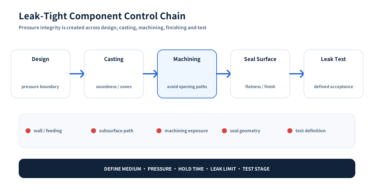
Typical failure paths and the buyer control
| Risk area | What can go wrong | What the RFQ / control plan should define |
|---|---|---|
| Thick section or abrupt transition | Local solidification shrinkage or internal discontinuity | DFM review, section transitions, feeding/gating strategy, critical-zone inspection if required |
| Machined bore or sealing face | Machining can open a previously enclosed discontinuity | Machining allowance, pressure-boundary map, finished-condition inspection/test |
| Threaded port | Porosity, damaged threads, burrs or poor seal geometry can create a path | Thread standard, gauge, sealing method, port-face requirement and leak test if functional |
| Gasket / O-ring face | Flatness, roughness, scratches or contamination can prevent sealing | Surface finish parameter, flatness/profile, visual standard, cleaning and protection |
| Assembly interface | Misalignment, damaged seals or incorrect torque can leak despite good castings | Interface drawing, assembly method and responsibility boundary |
| Test definition | “Leak test required” is too vague to compare suppliers | Medium, pressure/vacuum, hold time, maximum leak rate or pass/fail criterion, sampling, stage of test |
Design the pressure boundary before designing the inspection
The best time to improve pressure integrity is before tooling. Useful design questions include:
- Can heavy sections and abrupt wall transitions be reduced?
- Can the pressure boundary avoid unnecessary intersections with large bosses or pads?
- Are internal passages cast/cored or drilled after casting, and what does that do to risk?
- Is enough material present for a stable sealing face without requiring excessive machining depth?
- Where can the part be fixtured without distorting the sealing geometry?
- Are gasket grooves, O-ring lands, threads and flange faces compatible with the selected seal technology?
These questions are process-dependent. The correct answer for investment-cast stainless steel may differ from aluminum die casting or a fully machined billet manifold.
Control the manufacturing route
Casting soundness is local, not just a general grade
Casting defects matter most when they intersect the functional zone. A harmless internal indication in a noncritical rib is not equivalent to an interconnected discontinuity crossing a thin pressure wall or machined seal face.
For investment casting, gating/feeding, section transitions, melt practice, shell/process stability and alloy behavior all influence soundness. The Investment Casting Institute defect atlas is a useful reminder that different defect mechanisms need different corrective actions; “porosity” should not be used as one catch-all diagnosis.
The buyer should therefore mark pressure boundaries and no-leak functional zones on the drawing instead of demanding an undefined “zero porosity” condition everywhere.
Machining can reveal the risk that casting inspection did not show
Machining does not create shrinkage porosity, but it can intersect a subsurface discontinuity and turn it into an open path. This is why machining stock and pressure integrity need to be planned together.
A 2024 peer-reviewed study in the International Journal of Metalcasting modeled connected porosity in pressure-tight castings and specifically notes that machining can open internal cavity networks to the surface. The implication for buyers is practical: evaluate leak performance in the finished machined condition when machining intersects the pressure boundary. Read the paper.
For critical faces, use only as much stock as needed to obtain stable geometry. Excessive removal can increase exposure risk and cost at the same time.
Sealing surfaces need their own acceptance language
A drawing that says only “Ra 0.8” may still be incomplete for a gasket or metal-to-metal seal. Depending on the joint, buyers may also need to control:
- flatness or profile;
- concentricity/runout relative to a bore;
- waviness or tool marks;
- scratches, dents and exposed pores;
- edge breaks and burr direction;
- cleanliness and corrosion protection;
- whether a coating/passivation step occurs before or after final verification.
The seal supplier's design requirements should take priority over generic roughness assumptions.
Verify the finished condition
Leak testing: define the method, not just the word “test”
Common industrial methods include hydrostatic pressure tests, air-under-water bubble tests, pressure-decay or mass-flow methods, vacuum methods and helium detection for very low allowable leakage. The right method depends on service medium, pressure, allowable leak rate, component volume, safety and production rate.
A supplier cannot quote or validate a meaningful leak test from the instruction “100% leak test” alone. Define at least:
- test medium;
- test pressure or vacuum level;
- stabilization and hold time where relevant;
- maximum allowable pressure loss / flow / leak rate or clear visual acceptance;
- whether the test is before or after machining, finishing and assembly;
- sampling or 100% requirement;
- record/traceability requirement;
- any test-fixture sealing assumptions.
Pneumatic tests store considerably more energy than hydrostatic tests, so equipment and procedures must be engineered and approved for the test. Do not increase pressure casually to “make the test stricter.”
NDT and leak testing answer different questions
Dye penetrant, magnetic-particle testing, radiography and other NDT methods may be appropriate for defined defect risks, but they do not automatically prove fluid tightness. Conversely, a leak test can demonstrate functional containment without characterizing every internal indication.
The inspection plan should link each method to a failure mode:
- NDT — detect defined surface/subsurface discontinuities under an acceptance standard;
- dimensional inspection — verify pressure-wall thickness, seal geometry and interfaces;
- leak/pressure test — prove functional containment under the agreed test condition;
- material verification / traceability — prove the correct alloy and lot/document chain.
More inspection is not always better if the acceptance logic is contradictory or undefined.
What about impregnation or repair?
Vacuum impregnation is used in some casting industries to seal interconnected porosity, particularly in aluminum applications. It should never be assumed acceptable for every product. The drawing, customer specification and service environment must determine whether impregnation, weld repair or other remediation is permitted, restricted or prohibited.
If impregnation is allowed, the sequence relative to machining and testing matters. The same 2024 pressure-tightness research shows why complex connected paths may not always be sealed simply because impregnation is applied.
For critical stainless or alloy pressure parts, buyers should state repair/impregnation restrictions explicitly in the RFQ rather than discovering the disagreement after first articles.
Qualify the supplier and RFQ inputs
Supplier-qualification questions for pressure-boundary parts
Ask the supplier to show how it controls the full chain:
- How is the pressure boundary identified during drawing review?
- Which casting/process controls address the critical zones?
- Which features are machined through or close to the pressure wall?
- How are sealing faces protected after machining?
- Are leak-test fixtures validated and maintained?
- Are pressure gauges, flow meters or leak instruments calibrated at the required interval?
- Can test records be traced to part number, revision, lot and date?
- Are rejected leak-test parts analyzed for mechanism rather than simply re-tested?
- Are impregnation or repair routes controlled by customer approval?
- For repeat programs, are process changes and sub-tier changes communicated before implementation?
These questions are more meaningful than asking a supplier to promise “zero porosity.”
RFQ takeaway
For a leak-critical casting or machined component, send the finished drawing plus service medium, operating/test pressure, pressure-boundary definition, sealing method, machined interfaces, leak-test method and acceptance criteria, NDT scope, repair/impregnation rules and required traceability. That information lets design, casting, machining and inspection be planned as one pressure-integrity system.