
Component challenge
A pressure valve body contains a defined pressure boundary as well as machined seats, stem bores, ports, threads or flange faces. The casting must provide sound metal in the areas that remain after machining. If a tool removes significant material from a locally heavy section, subsurface discontinuities can become part of the final sealing or pressure surface.
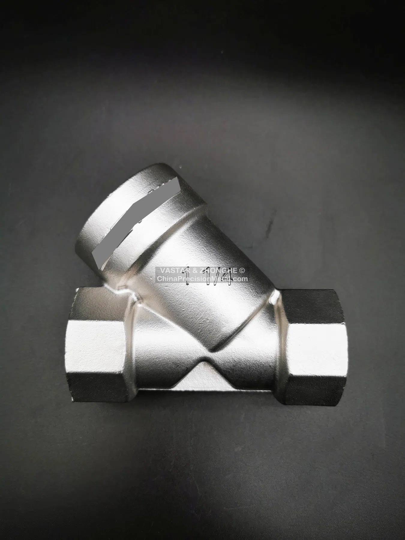
The valve and flow-control parts in our existing portfolio demonstrate the relevant component family. Exact customer geometry, pressure and acceptance data remain project-specific.
Process planning priorities
- Mark the complete pressure boundary during DFM review.
- Avoid abrupt section changes and isolated mass around bosses and ports.
- Position gates and feeders with critical machined zones in mind.
- Define whether weld repair or impregnation is allowed.
- Sequence heat treatment, machining, cleaning, NDT and pressure testing explicitly.
Machining and test route
The first operations create stable datums for port location, sealing seats and stem alignment. Cutting conditions and clamping should minimize distortion of the pressure boundary. Dimensional inspection verifies the relationship of bores, seats and faces; penetrant, ultrasonic or other examination can be assigned according to the drawing.
Hydrostatic testing is generally preferred where the specification permits because stored energy is lower. Pneumatic testing may be selected for gas leakage sensitivity or service simulation, but it requires appropriate fixtures, guarding and procedures. The test stage should match the delivered condition, normally after final machining and cleaning.
Useful RFQ information
Provide design pressure, test pressure, test medium, hold time, leakage criterion, pressure-boundary drawing, material standard, NDT level, repair policy, critical sealing dimensions and annual quantity.